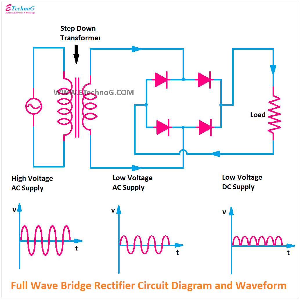
Circuit Diagram Of Bridge Type Full Wave Rectifier Full Wave
[diagram] 24v rectifier wiring diagram Half wave bridge rectifier circuit diagram Rectifier circuit circuits current alternating relay convert
Full Bridge Rectifier Circuit Diagram
Bridge rectifier circuit, construction, working, and types Bridge rectifier circuit diagram and waveform What is single phase full wave controlled rectifier? working, circuit
Full wave bridge rectifier
Rectifier operation diode diodes biased d1 กระแส engineeringtutorialFull wave bridge rectifier circuit diagram and working principle Full wave bridge rectifier – circuit diagram and working principle 4dfFull wave bridge rectifier operation.
What is the function of rectifier cheaper than retail price> buySimple bridge rectifier circuit Full wave bridge rectifier operationExplain full wave bridge rectifier with diagram.

Full wave bridge rectifier download scientific diagram
Full wave rectification diagramFull-wave bridge rectifier circuit Bridge rectifier input and output waveform at cheryl sherman blogFull bridge rectifier circuit diagram.
Full wave bridge rectifier diagramDraw the circuit diagram of a full wave bridge rectifier and explain The full-wave bridge rectifierRectifier bridge wave full operation half animation negative gif biased reverse current cycle d1 tools d3 d4 conduct input forward.


The Full-Wave Bridge Rectifier - Last Minute Engineers
![[DIAGRAM] 24v Rectifier Wiring Diagram - MYDIAGRAM.ONLINE](https://i2.wp.com/theorycircuit.com/wp-content/uploads/2018/03/full-wave-bridge-rectifier-circuit-diagram.png)
[DIAGRAM] 24v Rectifier Wiring Diagram - MYDIAGRAM.ONLINE

Full-Wave Bridge Rectifier Circuit

Full Bridge Rectifier Circuit Diagram

Full Wave Bridge Rectifier – Circuit Diagram And Working Principle 4DF

Full Wave Bridge Rectifier

bridge rectifier circuit diagram and waveform - Wiring Diagram and

Bridge Rectifier Circuit, Construction, Working, and Types
what is the function of rectifier Cheaper Than Retail Price> Buy

Draw The Circuit Diagram Of A Full Wave Bridge Rectifier And Explain